Note: For the 2019 Edition of the Pi Dramble, I am using the Blinkstick Nano over USB, since I lost the use of the Pi GPIO headers to the PoE HAT. But either way works great, and I still have all the RGB LED scripts in the source code if you're interested in building and using your own RGB LED boards!
Since the main purpose of the Dramble is to demonstrate Ansible deployments, it’s nice to be able to visualize the process. Since the Raspberry Pi has a 40-pin GPIO header with many software-controlled pins, it’s relatively easy to interface with external circuits to indicate status visually. One of the simplest circuits is an LED, which requires a resistor, an LED, and a connection between the LED and ground/3.3V on the Pi.
In our case, we can wire up a little board with a bright RGB LED so the Pi can display its status or other information using any color in the rainbow, and can even fade the LED in and out so the Pi looks like it’s ‘breathing’ (using Pulse-Width Modulation, or PWM for short)!
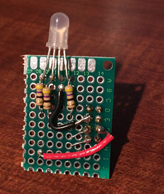
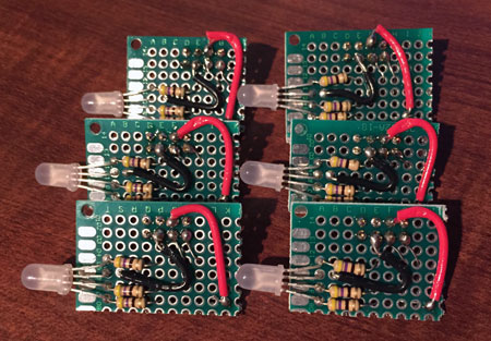
For my own Dramble, I’ve built six such RGB LED boards (one is pictured above), and I used the following parts to make each board:
- 6x RGB LED (5mm common cathode)
- 6x 2x4 pin female headers
- 2x 4x6cm double-sided prototype PCB (each cut in half, twice, so I had 8 to work with)
- 18x 470Ω resistors
- 1x Roll of 22AWG hook up wire (for a couple trickier connections)
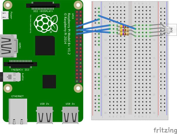
For each board, I designed the circuit using a breadboard, then diagrammed it in Fritzing:
Once I had the basic circuit design, I cut up a prototyping board and started playing around with a layout that would let the board plug directly into the GPIO using a 2x4 pin header, and have the LED facing directly out the front of the Pi. This way the ‘front’ of the Dramble could have all the LEDs nicely lined up vertically with each Pi. Here’s a picture of the beginnings of the circuit, from the underside (the female header plugs into the Pi directly):
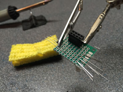
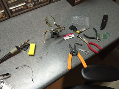
Using the assortment of tools pictured below (the most important tools are a soldering iron and solder, a wire stripper, and a needle-nose pliers), I soldered together all the boards in a couple hours, then tested them on an older Pi B+ (I didn’t want to learn that I bridged the wrong connection on one of the boards and fry a Pi 2!):
When complete, I had six nearly-identical boards (two were a little narrower, so connections were a little tighter), which I plugged into one of the Dramble Pis in the proper location on the GPIO port:
Once I had these boards wired up and ready to go, I wrote a few small Python scripts to control the LEDs (mostly for fun—the main one I’m using for the Dramble demonstrations is the simple rgb script that turns on one color at a time).
See the scripts in the repository:
- rgb - for setting one of the RGB colors
- colors - for setting arbitrary colors using PWM
- fade - fade a color in and out for a ‘breathing’ effect
- led-log-monitor - for toggling an LED on each write to Nginx’s access log
Ansible then copies these scripts into the user’s path as executables on each of the Dramble servers, so Ansible playbooks can call them with something as simple as command: rgb red to switch the LED to ‘red’ mode, or command: rgb off to switch the LED off.
Here’s a video of the LEDs in action (click the image to watch on YouTube):
